The internal structure of the security camera

As mentioned in the previous chapter(Security camera classification), according to the different output video signals, we can divide security cameras into three categories: analog, digital, and network. Different types of cameras have different internal components and mechanisms, such as analog and digital cameras, which only have image processing and no video image encoding.

The internal structure and composition of the camera are introduced here for the sake of simplicity. On the whole, we can divide the interior of the security camera into three major parts: image capture, video image processing and coding, and signal output .

Image capture

The image acquisition of the camera is mainly completed by the lens and the image sensor on the chip. The light passes through the lens and enters the sensor on the chip. The sensor is responsible for converting the received optical signal into an electrical signal, and then handing it over to the subsequent unit on the chip for processing.

For video capture, please refer to Video parameters in security cameras.

The focal length of the lens (fixed focus, zoom), aperture, quantity (multi-lens used in multi-eye cameras), effective pixels, etc. will affect the signal sent to the sensor, thereby affecting the final imaging effect.

For the related concepts of the lens and its specific application in the security industry, please refer to the following chapters: Lens of security cameraFisheye lensDepth of field of Security video camera, and Camera selection based on pixel density.

After the light reaches the sensor, it first performs the preliminary processing of converting the light signal into an electrical signal. The main performance parameters of sensor include target size, effective pixels, low-light performance and so on. These will also affect the final imaging effect. For the parameters and performance of the sensor, please refer to Security image sensorStarvis full-color camera technologyWide dynamic function of security camera and other chapters.

Image processing, video coding

The electrical signal converted by the sensor needs to be delivered to the processor on the camera chip for image processing, video encoding and other operations.

The processor is a very general term, similar to the CPU of a computer or mobile phone. For cameras that output analog or digital signals, the processor here mainly refers to ISP, that is, Image Signal Processor.

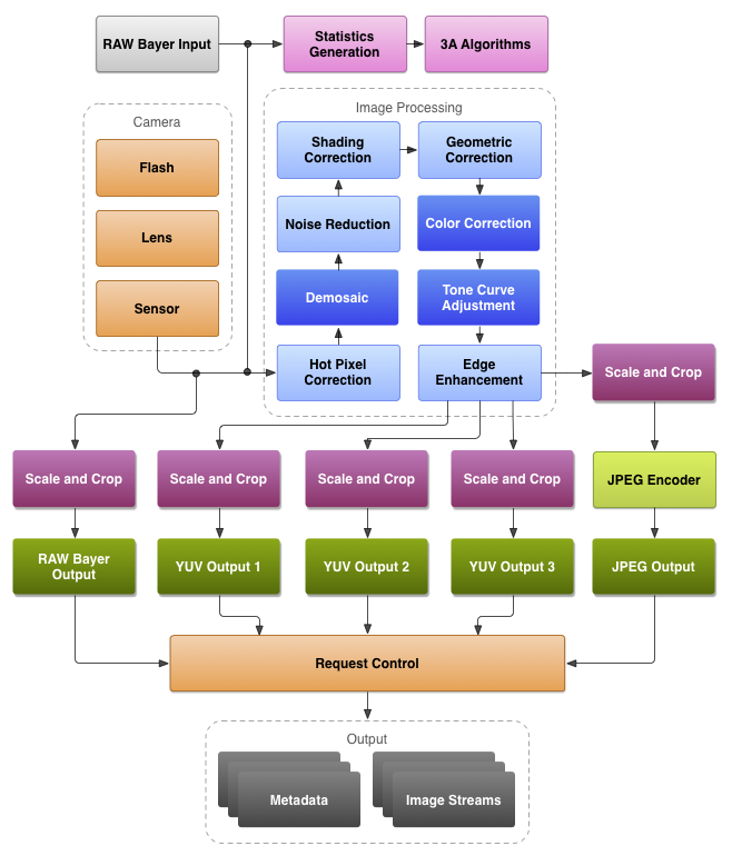
The main work of ISP includes:

  • DEMOSAIC, translated into Chinese is anti-mosaic. Each pixel signal output by the sensor contains only one color data among R, G, and B. This kind of data is bayer data, which is commonly referred to as RAW data. Obviously, the color information reflected in RAW data is not true color information. DEMOSAIC’s job is to calculate the true color represented by each pixel through an interpolation algorithm, that is, to convert the Bell image into a true color image.
  • 3A control. It is a collective term for Auto Focus (AF), Auto Exposure (AE) and Auto White Balance (AWB). This is the core part of ISP comparison, and the quality of processing is directly related to the final output image effect. ISP can realize auto-focusing through various auto-focusing algorithms such as CONTRAST AF, PDAF, LASER AF, etc., so that the target can be clearly imaged on the sensor. Exposure mainly affects the brightness of the image. ISP can control the degree of exposure to make the image brightness appropriate. White balance is related to color temperature and is used to measure the color authenticity and accuracy of an image. The automatic white balance function strives to accurately restore the original color of the target in various complex scenes.
  • Gamma correction. The response of the sensor to light is different from the response of the human eye to light. Gamma correction is to make the image look in line with the characteristics of the human eye.
  • Image cropping. That is, changing the size of the image can be used to output images of different resolutions. For example, the original resolution of 2048*1536, 4:3 is cropped to 2304×1296, and the resolution of 16:9 is more in line with the widescreen visual effect. Or a 5MP sensor, and it can also support different resolutions such as 4MP, 3MP, and 1080P.
  • Intelligent Algorithm. Used to identify specific targets, such as face recognition, human shape recognition, license plate recognition, etc. ISP uses various intelligent algorithms to accurately identify specific targets. Of course, in the network camera, the intelligent algorithm can also be built into the encoding chip. At the same time, intelligent algorithms and structured data functions can be placed in the sensor. For example, Sony’s AI sensor (SONY IMX500/501) has achieved direct output of structured data.
  • Dynamic Range. The dynamic range is the light and dark range of the image. ISP processing makes the dark part of the target image not under-exposed, and the bright scene is not over-exposed. In addition to the dynamic range processing supported by the ISP, the image sensor also needs to support the dynamic range (HDR) function. For details, please refer to the “Wide dynamic function of security camera” section.
  • The image is stable and anti-shake. The main function is to prevent the image from being blurred due to the slight shaking of the camera.

In addition to the above work and processes, ISP’s functions also include noise reduction, contrast, saturation, sharpness, etc. Due to the technical accumulation of different manufacturers, different solution providers, and differences in algorithms, the image effects of cameras with exactly the same hardware solution will be different.

The analog optical signal is converted into a digital signal by the sensor, and after ISP processing, it can directly output the image of the digital signal, such as an SDI camera. It can also undergo digital-to-analog conversion again to convert the digital signal into an analog signal for output, such as analog SD cameras with traditional cvbs signals, and high-definition analog cameras such as AHD/CVI/TVI/XVI.

On the other hand, the digital signal can also be encoded and output and transmitted through the network, that is, a network camera. The encoding at this time requires a special encoding chip to complete. It should be noted that most of the current encoding chips have integrated ISP functions.

For processors with video encoding functions, we generally call them CPU, DSP or SOC. Strictly speaking, there is a difference between the three. But for the processing chip of a security camera, it is not bad to call it CPU, DSP or SOC. In order to unify and follow the manufacturer’s customary naming, we call the processors that support video encoding functions SOC.

SOC, or system on chip, can be regarded as a three-in-one processor, ISP, and encoding chip. The following is a block diagram of a typical security video encoding chip:

From this we can see that its main structure is divided into Quad Core Arm® Cortex®-A53 (ie processor), Image Signal Processor (ISP), Video Codec. The front end can be connected to sensor, audio, alarm and other equipment. In order to support the operation of the system, there are running memory and internal storage. It can directly extend WiFi/4G, SD card storage, etc., and can output analog/digital video, audio, alarm, network, serial port (485, 232) and other signals.

The core function of SOC is video encoding. For example, the typical SOC chip provided above supports three video encoding methods: H.264, H.265, and MJPEG. Related concepts of video coding have a detailed introduction about video coding in the section, so I won’t go into details here.

At this stage, with the development of chip technology and AI smart algorithms, more SOC manufacturers have built smart functions into SOC chips, which are more, more powerful and more scalable than those built into ISP.

Signal output

The video signal, audio or other signals processed by ISP or SOC can be output as analog, digital and network signals as required.

  • Analog signal. After the electrical signal of the video image is processed by the ISP, it is converted into an analog signal by D/A and output through the BNC connector. Common analog video signals include standard definition CVBS, high definition AHD/TVI/CVI/XVI, etc. Theoretically, high-definition AHD/TVI/CVI/XVI signals can transmit audio, alarm, and control signals while transmitting video signals.
  • Digital signal. After the electrical signal of the video image is processed by the ISP, the digital signal is no longer directly output through D/A conversion. The common output interface can be a BNC header or an HDMI interface. Such cameras are mainly SDI cameras. The HDMI interface can transmit audio while transmitting digital video signals.
  • Internet signal. The digital signal is encoded by the encoding chip, and then can be transmitted through the network. This kind of network signal needs to go through the corresponding decoding to display the video image. Common decoding equipment and methods include the corresponding computer client, NVR, video decoder, network matrix, etc. On the other hand, audio, alarm, RS485 and other signals can also be encoded together with the video signal and then transmitted over the network.

Transmission in Surveillance Security

Transmission is signal propagation through various means (via media such as wire, coaxial cable, microwave, optical fiber, or radio frequency, etc.). There are two points in this. One is the means of transmission, that is, the transmission medium used, and the other is the signal to be transmitted.

The signals that need to be transmitted in the security system mainly include power, video, audio, alarm I/O, control signals, etc.

The main transmission methods and media are: coaxial cable, twisted pair, optical fiber, wireless (Wi-Fi and 4G, etc.), microwave, satellite, etc.

The details are described below.

Transmitted signal
Power signal
Security cameras generally use DC12V power supply, some dome cameras use AC24V power supply, and some home Wi-Fi smart cameras use DC5V power supply.

Hard disk video recorders DVR/NVR, ordinary switches generally use DC12V power supply or directly use AC220V power supply.

The POE switch uses AC48-52V power supply.

Back-end equipment, such as various servers, matrixes, and TV walls, generally use AC220V power supply.

Video signal
As mentioned in the article on the classification of security cameras, according to the different output signals, cameras can be divided into three types: analog, digital, and network.

An analog signal refers to a signal whose mathematical form is a continuous function in the time domain, which corresponds to a digital signal.

The analog video signal transmits a set of brightness and chrominance data of a video image that changes over time. Expressed by a digital function, time is the independent variable and the signal itself is the dependent variable. This function takes values ​​continuously on the time axis.

If only sampling at a fixed time node, such a signal is called a discrete-time signal, and a finite word length is used to represent the value of all sampling points. Such a discrete-time signal is called a digital signal.

Conceptually, a digital signal is a quantized discrete-time signal, and a discrete-time signal is an analog signal that has been sampled.

Because the value is continuously taken, it is obvious that the analog signal is more susceptible to noise interference. At the same time, almost all transmission media, such as coaxial cables, radio waves, optical fibers, etc., can be applied to digital or analog signals, but digital signals can use these media more effectively than analog signals.

Network signals, to be precise, should be called encoded digital signals, which are transmitted through a computer network, and they are still digital signals.

Audio signal
Sound is a sound wave generated by vibration, which is transmitted through a medium (gas, solid, liquid) and can be sensed by human or animal auditory organs.

The frequency of sound is generally expressed in Hertz, recorded as Hz, which refers to the number of periodic vibrations per second. The decibel is a unit used to express the intensity of a sound, denoted as dB.

The audio signal is the same as the video signal, and the audio is simulated by the analog signal, so the audio signal can be transmitted through the same medium as the video signal. In particular, audio can also be encoded like video signals and transmitted over the network.
For more details, please refer to the article on Audio Function in Network Camera.

Control signal
The control signals in security mainly include RS-485 pan/tilt control signal and RS-232 serial port signal.

RS-485 uses the voltage difference between the two ends of the cable to represent the transmission signal, and the different voltage differences are respectively identified as logic 1 and logic 0. It is valid when the voltage difference between the two ends is at least 0.2V and above. Any difference not greater than 12V or not less than -7V is considered correct for the receiving end.

RS-485 only specifies the electrical characteristics of the receiving end and the transmitting end. It does not specify or recommend any data protocol. (In the early use of the PTZ control function, you need to set the address code, protocol, and baud rate of the dome camera. Now the requirements are not so strict, and any protocol or baud rate may be able to control the PTZ equipment normally)

RS-485 is recommended to be used in point-to-point networks, linear and bus types, not star or ring networks. If you must use a star network, you need to use a special RS-485 splitter/repeater.

RS-232 is an interface standard for serial data communication formulated by the Electronic Industries Alliance (EIA), and is widely used in computer serial interface peripheral connections.

In the RS-232 standard, characters are transmitted serially in a serial bit string one after another. The advantage is that there are fewer transmission lines, simple wiring, and a longer transmission distance.

The cables and connectors used by RS-232 may be 3 to 25 pins, and the typical application is 4 to 6 pins.

RS-232 serial communication requires multiple settings in the software settings. The most common settings include baud rate, parity, and stop bit.

Alarm I/O signal
The alarm input and output signals are generally high and low levels or switch values. Its essence is a digital circuit.

The main problem studied in digital circuits is the logical relationship between the state of the output signal (“0” or “1”) and the input signal (“0” or “1”), that is, the logical function of the circuit. (Under positive logic, “0” is low level, “1” is high level, and there is no clear boundary between high and low levels)

There is a detailed description of the alarm input and output interface and signal in the article on the external interface of the camera, which will not be repeated here.

Transmission equipment and media
For the requirements of various cables used in security, please read the article Cables used in security. Here mainly talk about some special transmission functions and others.

Power line transmission
In addition to transmitting power signals, power lines can also transmit video signals, network signals, etc., with the help of power carrier technology.

Power line carrier communication is PLC, which is the abbreviation of English Power line Carrier. Power line carrier is a unique communication method of power system. Power carrier communication refers to the technology that uses existing power lines to transmit analog or digital signals at high speed through carrier waves. The biggest feature is that there is no need to re-establish the network, as long as there are wires, data can be transmitted.

When using power lines to transmit video signals, when network signals, you need to use the corresponding power line bridge, similar to a wireless bridge, one transmitter and one receiver, or many-to-one use.

Power line carrier transmission problems:

It can only be transmitted within the area of ​​a distribution transformer;
It can only be transmitted on single-phase power lines;
The power line causes a high reduction in the carrier signal;
The power line has inherent impulse interference.
Because of the above drawbacks, power line transmission technology is only a useful supplement, and it is difficult to apply and develop on a large scale.

Coaxial cable transmission
Similar to power carrier technology, coaxial cable can also be used to transmit network signals. This technology is called EOC (Ethernet Over Cable).

Similarly, EOC transmission also requires the help of corresponding bridges, one for transmitting and one for receiving, or many-to-one use.

The main problems of EOC: poor anti-interference ability, short transmission distance, and numerous standards. More importantly, network bandwidth has long been popularized, and the market stock using coaxial cable TV is becoming less and less. Therefore, it is less and less necessary to use EOC to transform the network.

Twisted pair transmission
Twisted pair is a kind of cable that is twisted into a spiral by two insulated double wires covered with plastic insulation material and copper cables inside.

In the two wires, the current induced by each wire is almost equal. The twisting of the two wires ensures that the average distance between the two wires and the source of interference is the same, and the effects are the same. The noise therefore generates a common-mode signal, which can be eliminated at the receiver only by detecting the differential signal.

Therefore, the twisted pair can reduce the attenuation in signal transmission, reduce crosstalk and noise, and improve the ability to suppress external electromagnetic interference.

Twisted-pair cables used to be mainly used to transmit analog signals, but they are now also suitable for digital signal transmission and belong to the transmission medium of information communication networks.

The use of twisted pair cables to transmit analog video requires the use of corresponding twisted pair transmitters (one receiver and one transmitter are used in pairs). When used to transmit digital network signals, use RJ-45 connectors, commonly known as crystal heads.

Multiple network cameras, network devices are transmitted through network cables, and they are gathered together using switches. For related introductions to switches, please refer to the articles on Switch Selection in Security Video Surveillance and PoE Power Supply.

Twisted pair specifications
EIA/TIA defines model specifications based on different qualities for twisted-pair cables.

Model Specification
CAT-1 is mainly used for voice transmission
CAT-2 transmission frequency is 1MHz, the highest transmission rate is 4Mbps
CAT-3 transmission frequency is 16MHz, the highest transmission rate is 10Mbps
CAT-4 transmission frequency is 20MHz, the highest transmission rate is 16Mbps
CAT-5 transmission frequency is 100MHz, and the highest transmission rate is 100Mbps
CAT-5e has low attenuation and low crosstalk
CAT-6 transmission frequency is 250MHz, transmission speed is 1Gbps, standard outer diameter is 6mm
CAT-6A transmission frequency is 500MHz, transmission speed is 10Gbps, standard outer diameter is 9mm
CAT-6e transmission frequency is 500MHz, transmission speed is 10Gbps, standard outer diameter is 6mm
CAT-7 transmission frequency is 600MHz, transmission speed is 10Gbps
CAT-8 transmission frequency is 2000MHz, transmission speed is 40Gbps

Fiber optic transmission
Whether it is a coaxial cable or a twisted pair cable, the transmission distance is limited. When a wired transmission is required for several kilometers or tens of kilometers, optical fiber is required.

Optical fiber, the full name of optical fiber (Optical fiber), is a fiber made of glass or plastic, and a light transmission tool that uses the principle of total internal reflection to transmit light in these fibers.

The tiny optical fiber is encapsulated in a plastic sheath so that it can be bent without breaking. Generally, the transmitting device at one end of the optical fiber uses a light-emitting diode or a laser beam to send light pulses into the optical fiber, and the receiving device at the other end of the optical fiber uses a photosensitive component to detect the pulses. Cables containing optical fibers are called optical cables. Because the transmission loss of information in optical fiber is much lower than that of electricity in wire transmission, and because the main production material is silicon, it has a large reserves and is easier to mine, so the price is very cheap, which promotes the use of optical fiber as long-distance information Transmission medium.

In addition to fiber-optic cables, fiber-optic data transmission requires the use of fiber-optic transceivers, which can be used in pairs for receiving and transmitting data. The optical fiber transceiver function can also be built into the switch, that is, the optical fiber interface (SFP) of the switch to realize the transmission of optical signals.

The use of light-emitting diodes to transmit multiple beams of light is called multimode fiber. It is a single-mode fiber that uses a laser to emit a single beam of light. Single-mode and multi-mode fibers cannot be mixed, and the corresponding optical transceivers cannot be mixed.

Generally, we call the optical fiber equipment that transmits network digital signals an optical fiber transceiver, and the optical fiber equipment that specializes in transmitting video signals is called an optical transceiver.

Fiber optic connector
Common fiber optic connectors are divided into FC and SC.
FC is the Ferrule Connector round with thread, which is mostly used on patch panels. SC is the Snap-in Connector card-connected square type, which is mostly used in routers and switches.

All of the above are wired transmission, and the wireless transmission is introduced below. In any case, the stability and reliability of wireless transmission are worse than wired transmission, and wireless transmission only exists as a useful supplement to wired transmission.

Wireless transmission
Wi-Fi
In theory, security equipment that uses wired network transmission, such as network cameras, DVRs, NVRs, etc., can expand the wired network to wireless Wi-Fi by adding a wireless Wi-Fi network card.

Wireless bridge
The transmission distance of wireless Wi-Fi is generally limited. For special needs, we can use high-power wireless bridges to wirelessly transmit network digital signals or video signals over a long distance.

Wireless bridges are also used in pairs, one for receiving and one for sending. Of course, it can also be used in many pairs. The transmission distance can be several kilometers to dozens of kilometers. When performing wireless transmission, there should be no obstacles between the bridges. When the distance is long, the antenna angle between the bridges needs to be adjusted to achieve the best wireless transmission effect.

Microwave transmission
Microwave communication refers to a comprehensive technology that transmits signals using microwaves with frequencies between 0.3 GHz and 300 GHz (wavelengths between 0.1 mm and 1 meter) as carriers. The millimeter wave band used in 5G communications is microwave.

Microwave communication is a communication that directly uses microwave as a medium, and does not require a solid medium. Microwave transmission can be used when there is no obstacle within a straight line distance between two points. Generally, a parabolic antenna is used to transmit and receive microwave signals.

Microwave communication has good disaster resistance performance, and is generally not affected by natural disasters such as floods, wind disasters, and earthquakes. However, microwaves are transmitted through the air and are susceptible to interference. The same frequency cannot be used in the same direction on the same microwave circuit. Therefore, the microwave circuit must be constructed under the strict management of the radio management department.

Satellite transmission
Radio communication uses electromagnetic waves to transmit signals. These waves are transmitted in a straight line, so they will be blocked by the curved surface of the earth. Therefore, communication satellites can be used to transmit signals on the surface of the earth to achieve long-distance communication on the ground.

The satellite orbit is high above the ground, the antenna beam can cover a large area of ​​the earth, and the radio wave propagation is not restricted by the terrain. The satellite is equipped with a transponder composed of receiving and transmitting equipment, which amplifies and shifts the frequency of the received signal and transmits it to the ground.